|
*2016 electrical update
*Defroster / fog switch / thermometer /
clock / voltage meter
At some point the electrical system in the car was satisfactory and it still
may have been if the engine was not replaced not for the fact that front lights
are so dim due to undersized wire gauge and new light bulbs require higher
current to produce designed amount of light from the filaments.
With exception of removed side markers in the rear, that tail part of the sub
harness does not need to be changed, there will be couple extra wires dangling
in the panels but that can be fixed by tying them up to the loom.
This leaves dash harness and engine bay harness. Since all the gauges in the
dash will be replaced, that harness will be thrown out and it will be divided
into 2. First part of the harness will contain ignition and all switches (door
pins, clutch, brake, lights, wiper) and be routed and tied to the firewall.
Second part of the harness will be instrument harness for all guages, OBD,
MIL/idiot ligts etc.
This leaves the engine bay harness. Since that harness is underrated would
have to be reworked to remove any unnecessary original engine circuits, it's
better to just have it thrown out and manufacture new one to accommodate not
just the LS1 requirements but also to upgrade lighting wiring.
2008-10-31
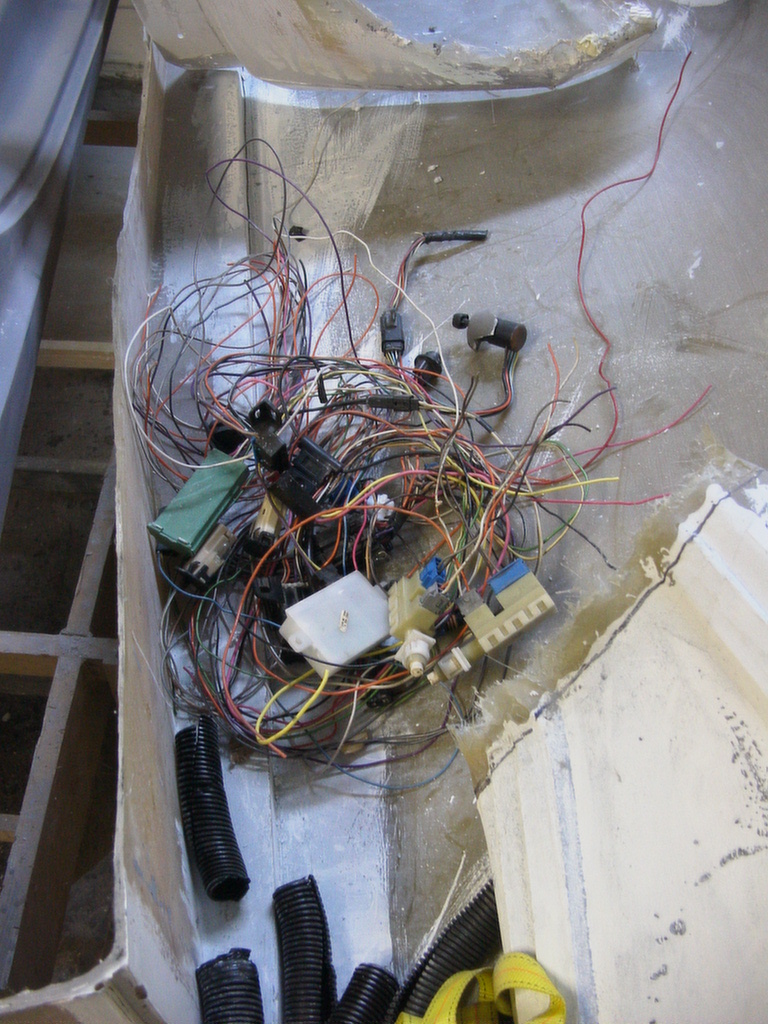
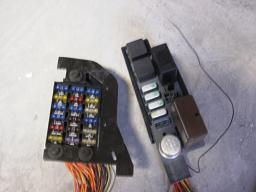
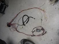
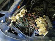
Ah and the fun begins.... on the left is fuse box out of 97 (?) Pontiac
Transport van, in the middle are some connectors and switches necessary for
pedals and interconnections that where past of the van under dash sub-harness.
To the very right are engine harness on the left and under hood sub-harness out
of 02 Camaro SS
2008-11-07
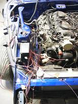
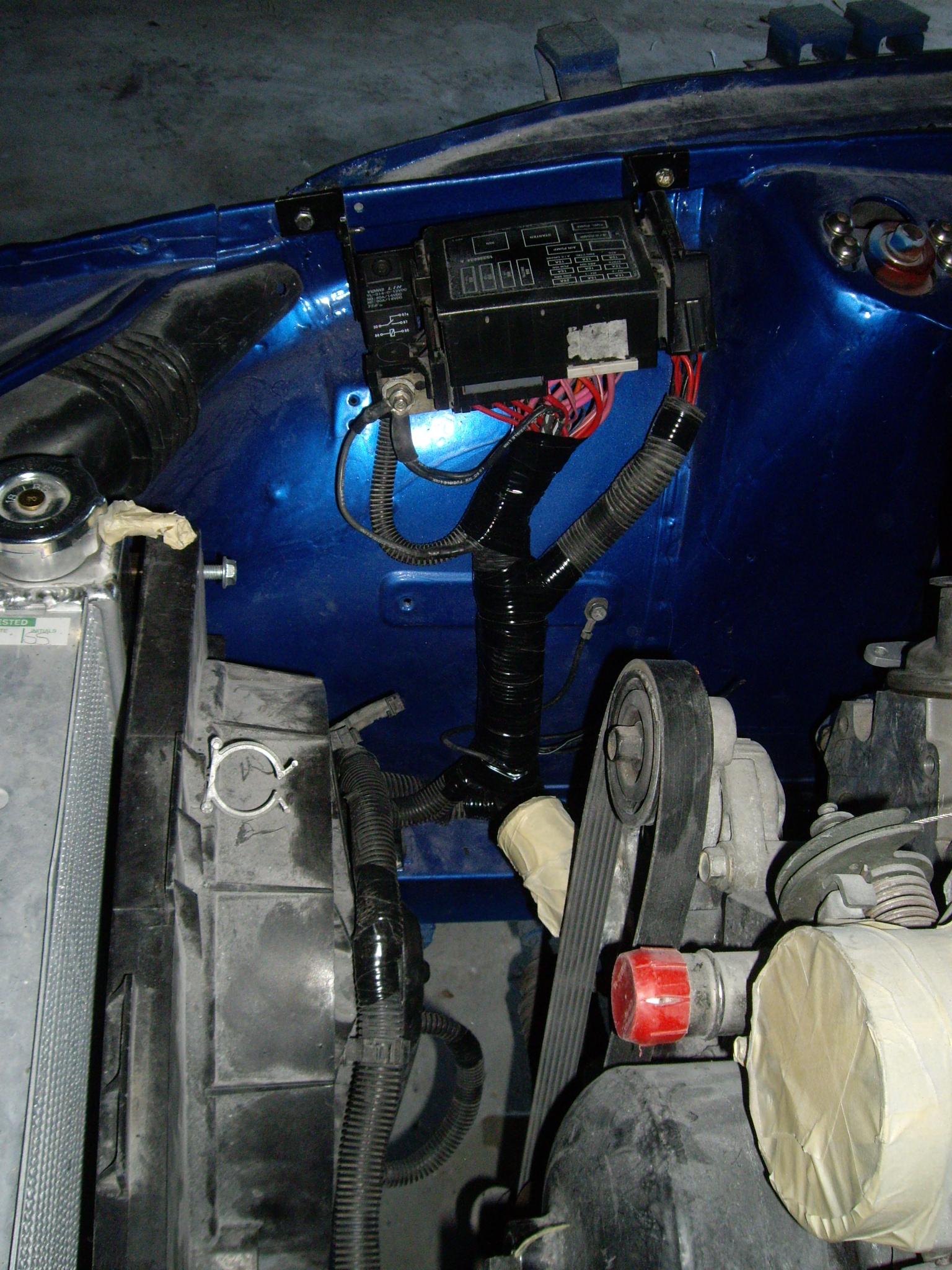
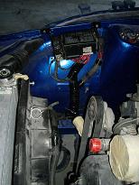
This is beginning of placing the engine bay fuse block. The block will have all
necessary fusing for the engine and front lights. Since the ignition switch is
not capable or running amperage for the engine and all accessory circuits it
will also have relays for the engine and front lights. It will also have relays
for cooling fans a fuel pump.
2008-11-08
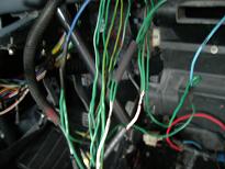
First few circuits have been routed.
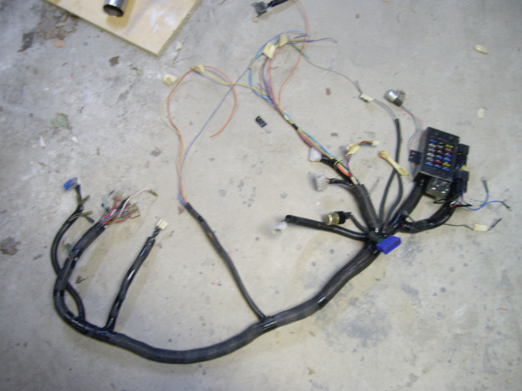
2009-03-17
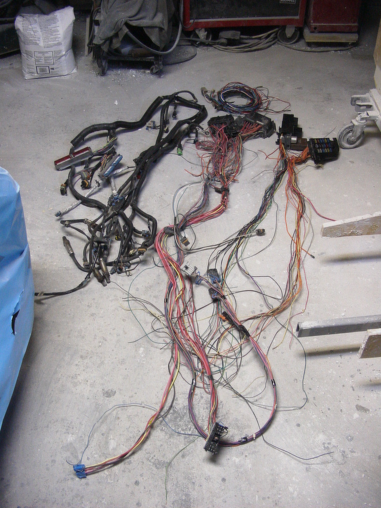
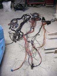
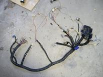
 After some weeks digging through schematics and figuring out what's needed and
what would be nice to have, this is the final harness for the engine bay. It
combines original 2 fuse block engine bay harness from 02 Camaro and adapts to Z
lighting.
After some weeks digging through schematics and figuring out what's needed and
what would be nice to have, this is the final harness for the engine bay. It
combines original 2 fuse block engine bay harness from 02 Camaro and adapts to Z
lighting.
OK semi complete..... need to add wiper wires, engine feedback to instrument
cluster wires and brake fluid reservoir switch wire. Those are just a matter of
putting through the grommet and tape it together.
2009-03-22
Fuse box section of the harness is completed. However mounting brackets need to
be changed to allow clearance so that hood can be closed
2009-03-28
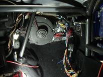
Beginning of first part of internal/switches sub-harness
2009-04-05
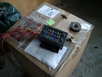 
Internal fuse box on the left and splicing method of wires to the right. Wires
are soldered together and heat shrink wrap it to seal.
2009-04-24
Switch section and fuse block sections ready to be joined together and
provide inter connect connectors to engine bay and tail harnesses
2009-05-12
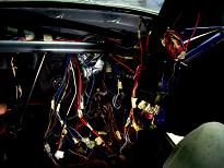
Semi finished switch harness on the left and installed on the right.
As it sits all engine relays, pedal switches and lights are functional. The
interconnection to the dash sub-harness will be completed at later time.
As to how the engine will run and if will run will be discovered later.
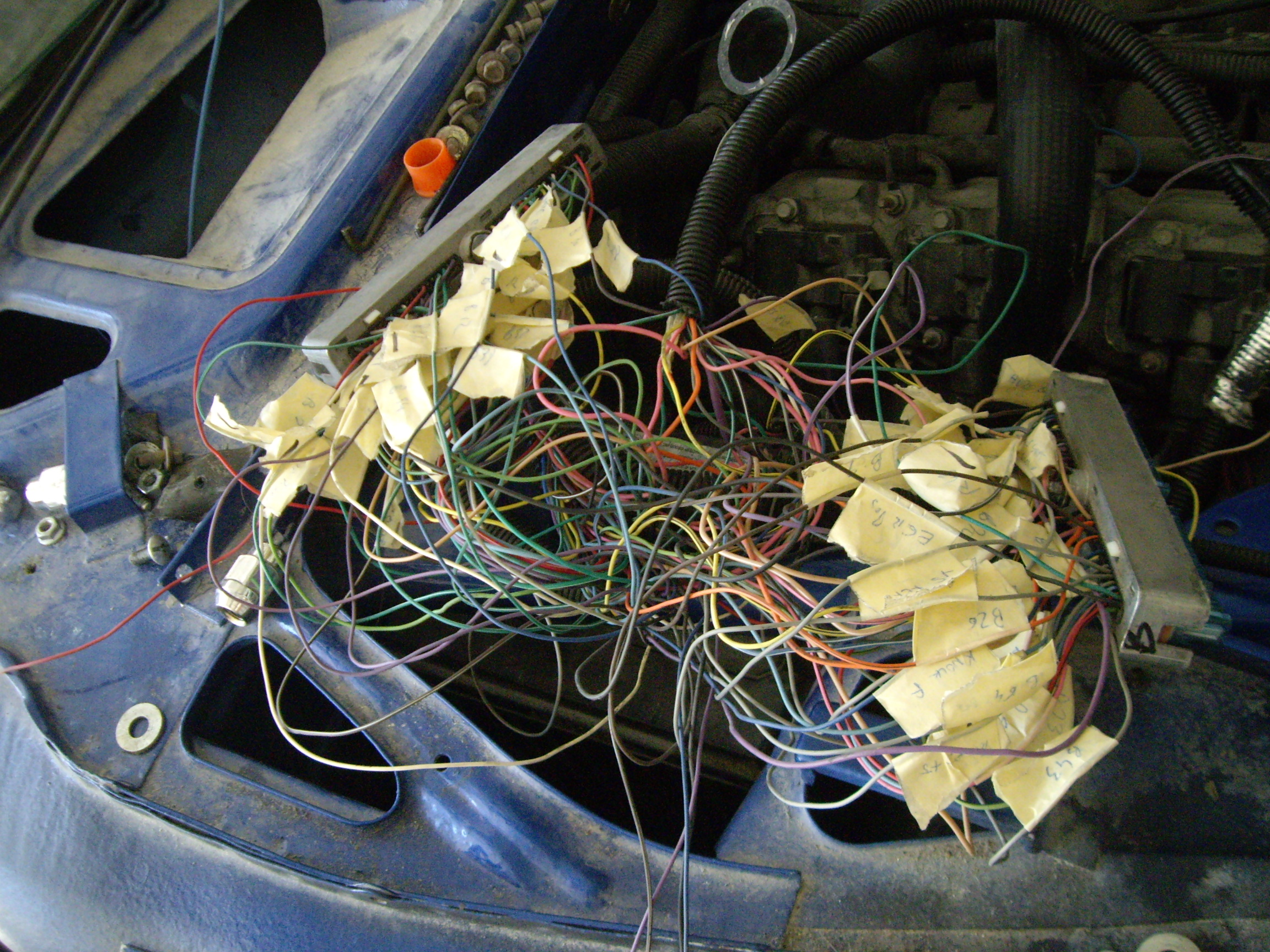
2009-09-20
 Well
tried to power up the PCM and start the engine, however ignition PCM fuse was
blowing after key was turned. After some research problem discovered with the engine harness was that it was pinned for 98 PCM
and the PCM we are working with is for 00-02 model year. As we do already have the newer PCM programmed for
our needs and though it may have been easier to just get model 1 of the PCM to
match the wiring connectors. We have opted out to keep the PCM and just rewire
the PCM connectors as it allow it to program the PCM with out removing it from
the car. Well
tried to power up the PCM and start the engine, however ignition PCM fuse was
blowing after key was turned. After some research problem discovered with the engine harness was that it was pinned for 98 PCM
and the PCM we are working with is for 00-02 model year. As we do already have the newer PCM programmed for
our needs and though it may have been easier to just get model 1 of the PCM to
match the wiring connectors. We have opted out to keep the PCM and just rewire
the PCM connectors as it allow it to program the PCM with out removing it from
the car.
The pin out of the PCM connectors are the only ones that need to be changed and
are found <here>.
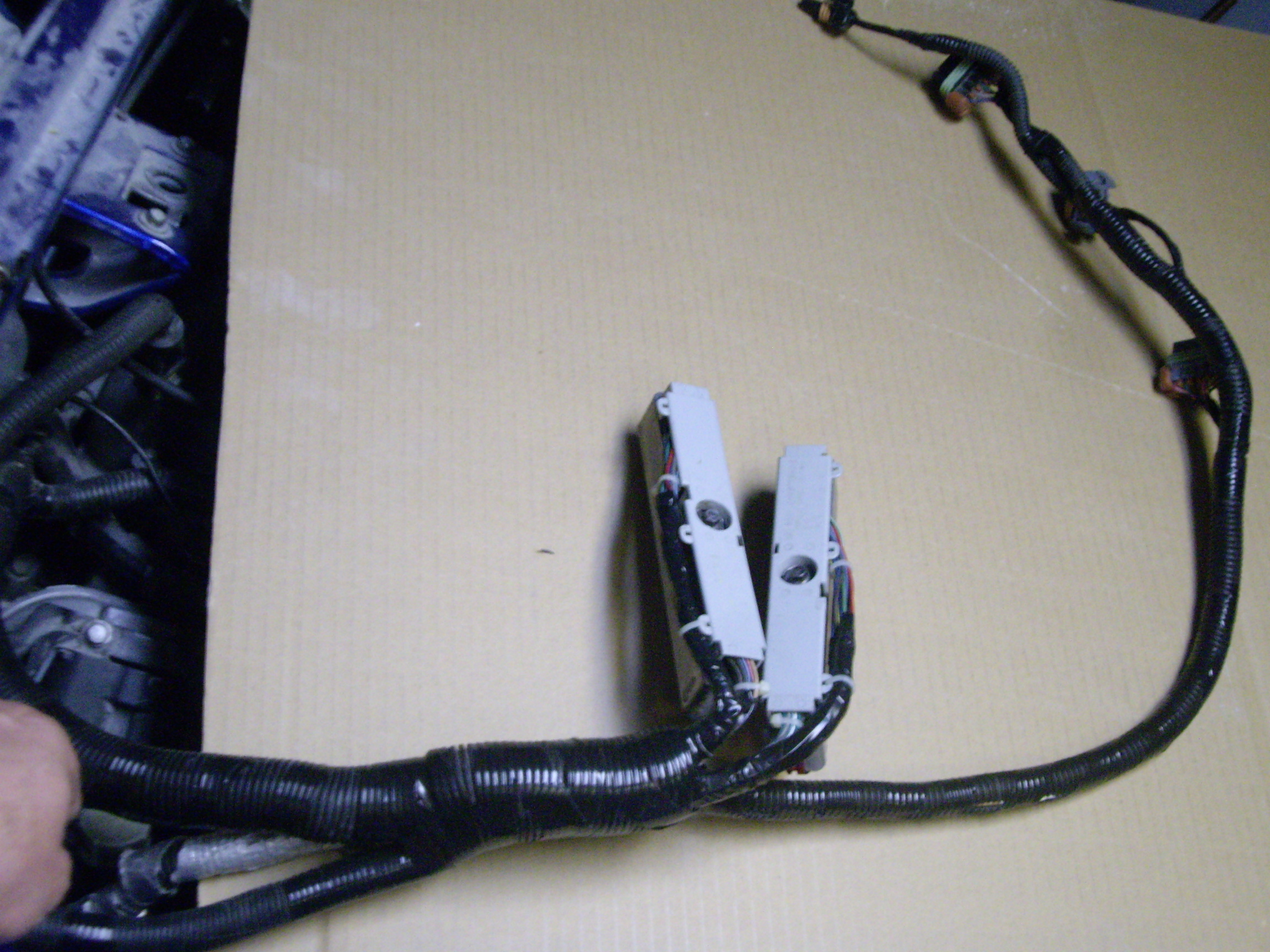
After the mess has been cleaned up from repinning both C1 and C2 connectors it
looks more. presentable though with relocation of
the wires, wire loom is about 2" shorter not that its a major problem its just
that it does not have as much of give to it and bit thicker around those
connectors which I may have to raise battery tray by 1/4".
2009-10-06
 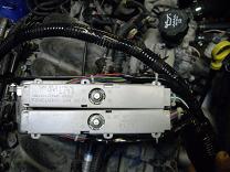
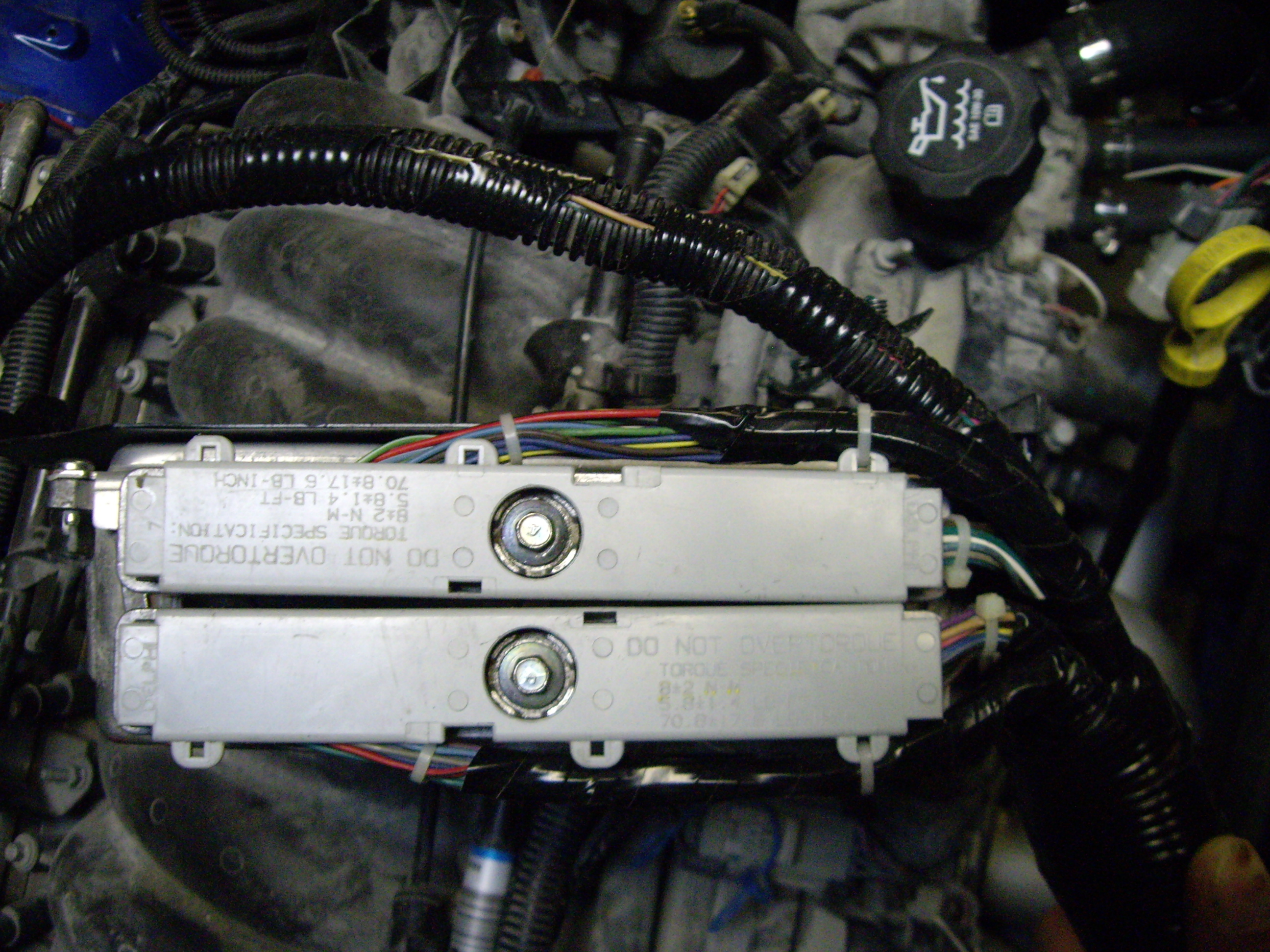
After rewrapping the loom and connected to the PCM. Notice the wires coming out
on opposite sides not like OE where one connector wires was pinched between the
connectors.
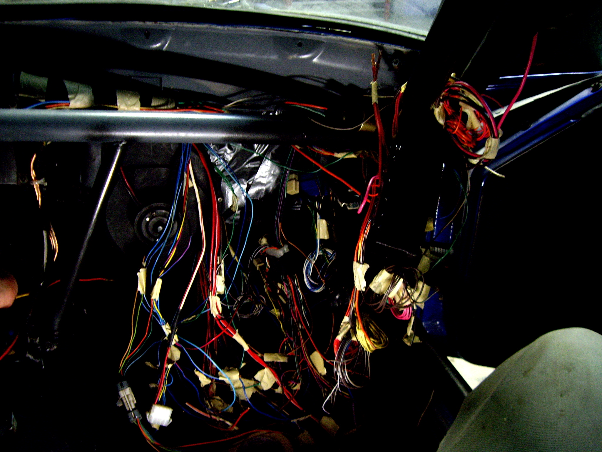
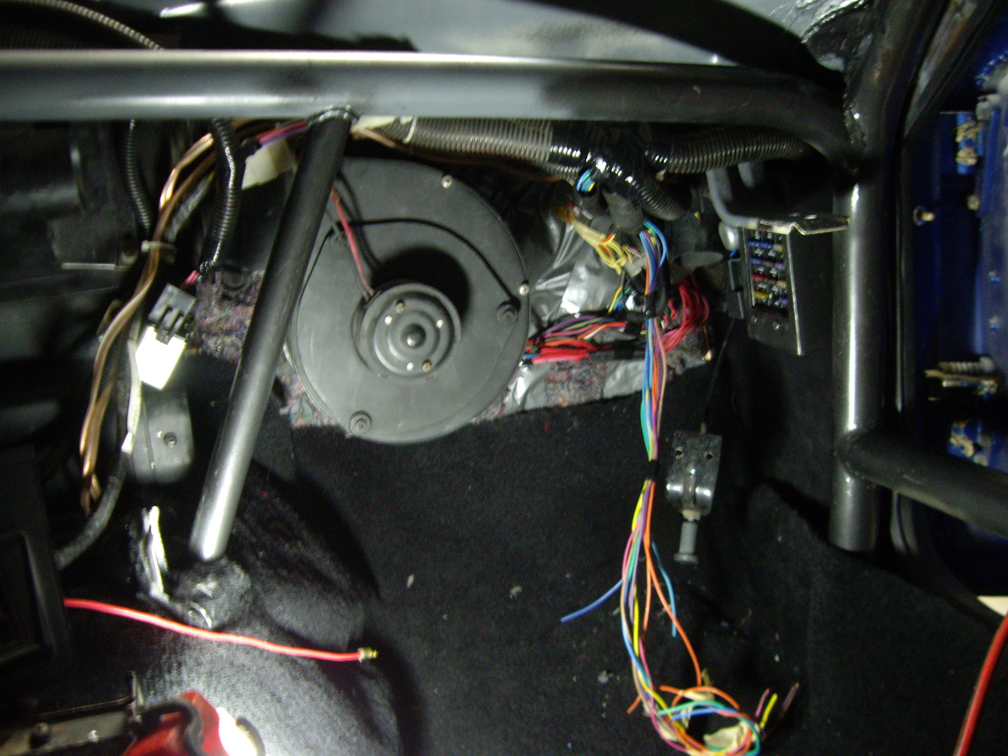
2009-11-11
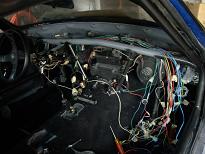
After discovering that the blower sub-harness had issues, I decided to rip
the dash out and make couple changes to the dash sub-harness. Changed lighting
connector for HAVC control added power for console courtesy light, added
illumination wire to radio, changed reverse light power source. Finalized
connections for Tach and Speedo plus couple other MIL lights. Dash is in for
final placement. Now all trim pieces can be put in place.
2016
electrical update
|